Potentiometer control LED dimmer use PIC16F877A Microcontroller and mikroC
In this tutorial we will learn how to LED brightness control use potentiometer. Here I am use PIC16F877A Microcontroller.
You can watch the video or read the written tutorial below.
PIC16F877A Microcontroller has two CCP module. CCP means Capture Compare Pulse Width Modulation(PWM). It generate different duty cycle pulse. The Analog output voltage of microcontroller depend on duty cycle. When duty cycle 0% than output voltage of CCP is 0 volt , duty cycle 50% output voltage 2.5 volt and duty cycle 100% out is 5 volt.
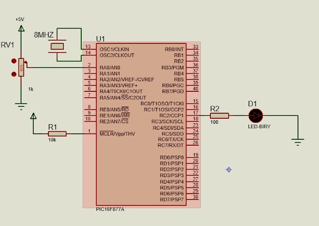
Circuit Schematic
In this project I am use Analog Channel 0 for analog voltage input. The output of CCP module depend on input analog voltage. When increase the input analog voltage the output of Duty Cycle increase. The Duty Cycle is proportional of input Analog voltage.
Project source code:
int i = 0;
float j =0;
float ADC_Value;
void main() {
     TRISA = 0XFF;                           // PORTA is input
     PORTA = 0X00;                           // Clear PORTA
     ADC_Init();                             // Initialize ADC module
     PWM1_Init(1000);                        // Initialize PWM1 at 1KHz
     PWM1_Start();                           // Start PWM1
     while(1){                               // Endless loop
              ADC_Value = ADC_Read(0);
              ADC_Value = ADC_Value * 4.89;
              ADC_Value =  ADC_Value /1000;
              i = ADC_Value * 20 ;
              j = (i*255)/100;
              // calculate the duty cycle for Pusle Width Modulation
              //duty cycle = (percent of duty cycle*255)/100;
              PWM1_Set_Duty(j);
             }

}
Download free source code


Post Comments