PORTB change interrupt in PIC16F877A microcontroller and mikroC
In this tutorial we will learn how to make PORTB change Interrupt with PIC Microcontroller. Here I am use PIC16F877A Microcontroller and mikroC PRO for PIC compiler.
You can watch the following video or read the written tutorial below.
Interrupt
Interrupt is a signal Microcontroller emitted by hardware or software indicating and event that needs immediate attention .
PORTB Change Interrupt Control Registers
OPTION_REG Register
The OPTION_REG Register is a readable and writable register, which contains various control bits to configure the TMR0 Prescaler / WDT postscaler.
OPTION_REG REGISTER

bit 7 RBPU: PORTB Pull-up Enable bit
1 = PORTB pull-ups are disabled
0 = PORTB pull-ups are enabled by individual port latch values
bit 6 INTEDG: Interrupt Edge Select bit
1 = Interrupt on rising edge of RB0/INT pin
0 = Interrupt on falling edge of RB0/INT pin
bit 5 T0CS: TMR0 Clock Source Select bit
1 = Transition on RA4/T0CKI pin
0 = Internal instruction cycle clock (CLKOUT)
bit 4 T0SE: TMR0 Source Edge Select bit
1 = Increment on high-to-low transition on RA4/T0CKI pin
0 = Increment on low-to-high transition on RA4/T0CKI pin
bit 3 PSA: Prescaler Assignment bit
1 = Prescaler is assigned to the WDT
0 = Prescaler is assigned to the Timer0 module
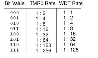
bit 2-0 PS2:PS0: Prescaler Rate Select bits

INTCON Register
The OPTION_REG Register is a readable and writable register, which contains various enable and flag bits for TMR0 register Overflow, RB Port change and External RB0/INT pin Interrupts.
INTCON REGISTER

bit 7 GIE: Global Interrupt Enable bit
1 = Enables all unmasked interrupts
0 = Disables all interrupts
bit 6 PEIE: Peripheral Interrupt Enable bit
1 = Enables all unmasked peripheral interrupts
0 = Disables all peripheral interrupts
bit 5 T0IE: TMR0 Overflow Interrupt Enable bit
1 = Enables the TMR0 interrupt
0 = Disables the TMR0 interrupt
bit 4 INTE: RB0/INT External Interrupt Enable bit
1 = Enables the RB0/INT external interrupt
0 = Disables the RB0/INT external interrupt
bit 3 RBIE: RB Port Change Interrupt Enable bit
1 = Enables the RB port change interrupt
0 = Disables the RB port change interrupt
bit 2 T0IF: TMR0 Overflow Interrupt Flag bit
1 = TMR0 register has overflowed (must be cleared in software)
0 = TMR0 register did not overflow
bit 1 INTF: RB0/INT External Interrupt Flag bit
1 = The RB0/INT external interrupt occurred (must be cleared in software)
0 = The RB0/INT external interrupt did not occur
bit 0 RBIF: RB Port Change Interrupt Flag bit
1 = At least one of the RB7:RB4 pins changed state; a mismatch condition will continue to set the bit. Reading PORTB will end the mismatch condition and allow the bit to be cleared (must be cleared in software).
0 = None of the RB7:RB4 pins have changed state
Circuit Schematic of external interrupt

Source code:
int i;
void main() {
     TRISB = 0X10;               // RB7 is input pin and other pin is output
     PORTB = 0X00;             // Clear the PORTB register
     INTCON.GIE = 1;       // Enable Global interrupt Enable bit
     INTCON.RBIE = 1;        // RB change interrupt Enable bit
     INTCON.RBIF = 0;        // Clear PORTB on change Flag bit
     OPTION_REG.INTEDG = 1;
     while(1){
              PORTB.F0 = 1;
              delay_ms(250);
              PORTB.F0 = 0;
              delay_ms(250);
              }

}
void interrupt(){
     if(INTCON.RBIF == 1){

                    for(i=0;i<6;i++){                // 6 time blinks
                                     PORTB.F1 = 1;
                                     delay_ms(250);
                                     PORTB.F1 = 0 ;
                                     delay_ms(250);
                                     }
                     INTCON.RBIF = 0;         // clear PORTB on change Flag bit
                    }

     }
Download free source code


Post Comments